We will present a tutorial on how to configure Failover in PfSense. That way, we can use one or more Internet links, and PfSense will use the second link when one link goes down.
The applicability of this configuration assumes that our company always has at least one active link to the internet. Or even a minimum redundancy of links with the internet in case of failures of some internet provider.
Tutorial Load Balance + Failover
Part 01: Configure Failover in PfSense
Part 02: Configure Load Balance with PfSense
Currently, with the increase of home working, having an alternative link to stay connected to the Internet becomes essential. In this way, we can use PfSense to manage the use of different Internet links.
For example, we could have the first link as the default internet provider and the second link as the internet routing via the cellular network. Then, if the default provider link goes down, PfSense could switch to using the cellular network provider link.
Configuring the test scenario
This session demonstrates how to create a test scenario so the reader can proof-of-concept failover in pfsense.
If you already have a real scenario to use, skip this section.
We are assuming that we already have a pfsense installation in virtualbox. If you still don’t have it, I suggest you do the steps described in the video below:
Let’s add a NAT Network interface in virtualbox. Thus, in our test scenario we will have two outputs to the internet, one through the virtualbox default NAT network and the other through a NAT network that we are going to create.
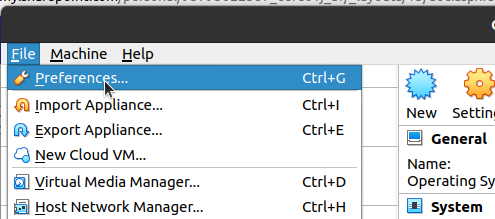
Initially we are going to select the File menu of virtualbox and then Preferences.
After that, we are going to select Network and we are going to click on the add icon.
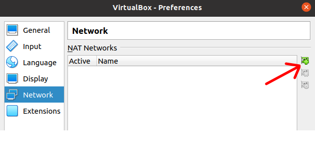
If you haven’t added a NATNetwork before, your first such network will be created.
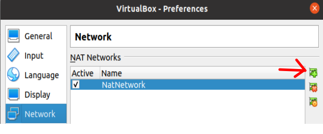
Now let’s click on the add new NATNetwork network icon again. That’s because we want to create a second NATNetwork.
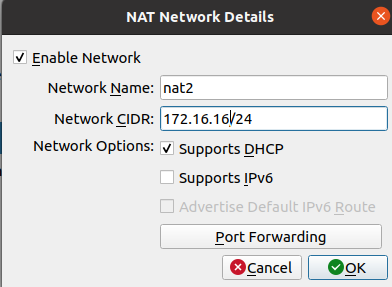
For the second NATNetwork we will name it “nat2”. Also, we are going to use the 172.16.16.0/24 subnet. It could be another network range of your choice.
(Note) It is important to leave DHCP support enabled. That way, we won’t have to manually enter IPs on machines that use this NATNetwork.
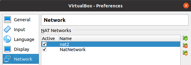
We can see in the figure below that there are two NAT Networks.
Configuring the Pfsense virtual machine
Now we are going to select the virtual machine that we are going to use for pfsense and we are going to click on Settings.

After that we go to Network and we are going to choose the types of networks that we are going to use in the network adapters.
On the first network adapter (Adapter 1) we are going to use VirtualBox’s default NAT network.
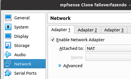
The second network adapter (Adpter2) we will use the interface in “host-only Adapter” mode. That way, we can access Pfsense’s WEB configuration interface using our real machine.
Note – Remembering that this second adapter will be used for LAN. So if you are accessing your pfsense from another network you must specify the correct network type here.
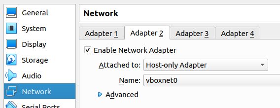
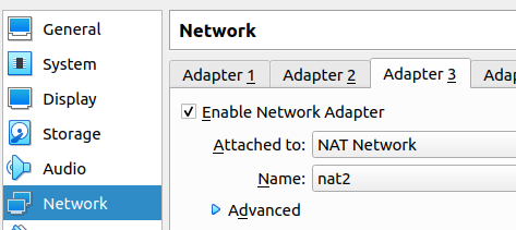
Next we will enable the third network adapter (Adpter 3) and we will add it to the Nat Network we recently created “nat2”.
Adding the second WAN to Pfsense
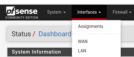
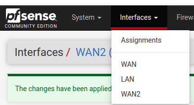
Now let’s start our virtual machine and access the pfsense web interface. Then, on the main menu, click on Interfaces and then on Assignments.
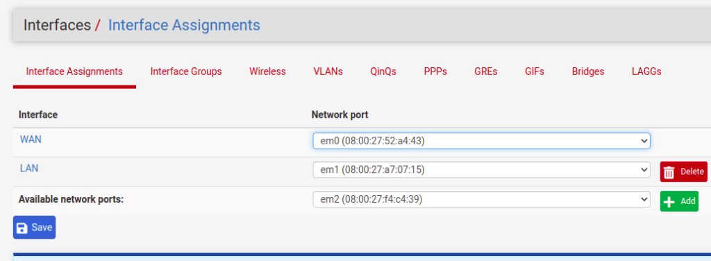
Note that we now have a new interface possibility. So, click on “+Add”
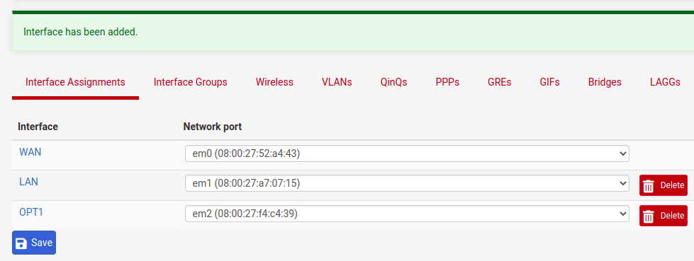
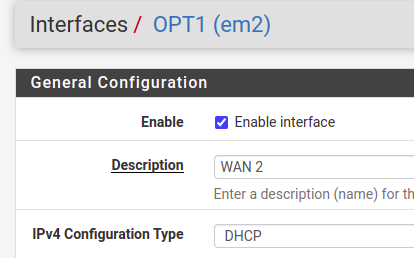
After clicking on “+Add” we will see a new interface with the name “OPT1”. So let’s click on “OPT1” and let’s edit.
Now, let’s change the name of the interface to “WAN 2” and let’s use the option to receive IP by DHCP.
Now let’s go to the bottom of the page and click on “Save”.

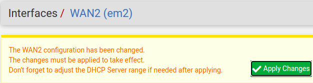
Okay, now let’s click on “Apply Changes”. That way, we’ll ensure that the changes we’ve made are applied.
Configuring PfSense Failover
Now we can see that we have a total of 3 interfaces.
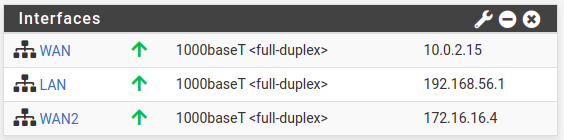
Also, if we go to the pfsense splash screen, we will see the IPs of each interface. In this way, we can see in the figure below that we have the LAN using an IP “192.168.56.1” that is being used with the virtualbox host only interface and the host machine. Then we have the IP “10.0.2.15” for the interface that is in NAT. And then we have the IP “172.16.16.4” for the interface that is in network NAT nat2.
As a result, we now have two WAN interfaces one for 10.0.2.15 and one for 172.16.16.4. In this way, we are emulating our scenario to have two different ISPs.
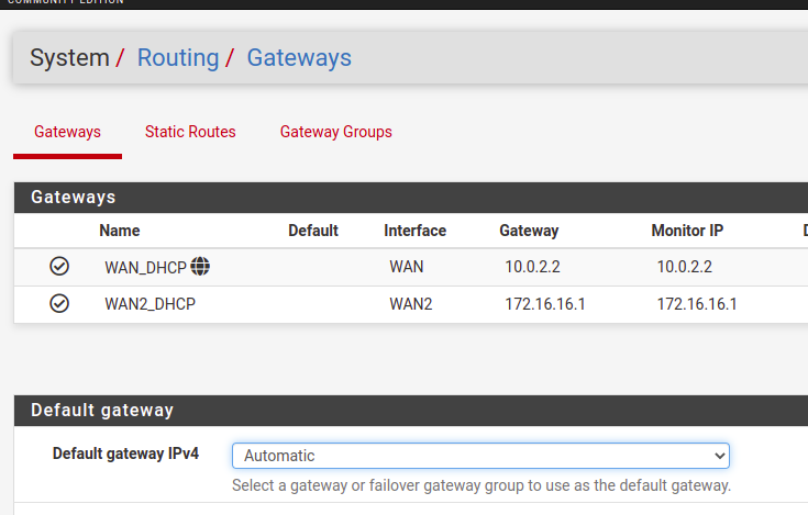
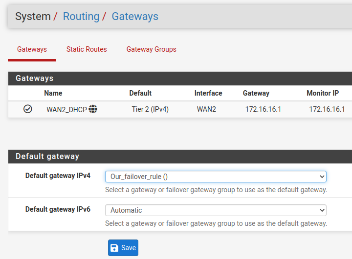
Now let’s click on System/Routing/Gateways. We can see that we now have 2 gateways, as in the figure below.
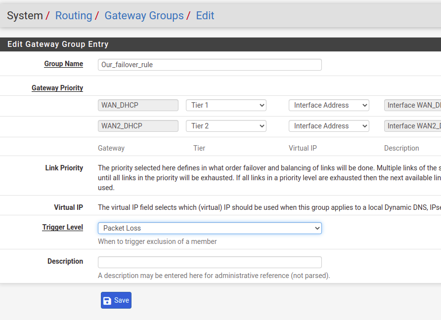
Now let’s click on Gateway Groups and create a group called “Our_failover_rule”. Within this gateway group, we will prioritize the use of gateways. This priority is achieved using the “Tiers”. Thus, the lower the “Tier”, the higher the priority of use.
In our case we are using “Tier 1” for “WAN_DHCP”, this is our first WAN. As for the other “WAN 2”, we will use “Tier 2”. In this way, we will use the first WAN as the main gateway, as it has a lower “Tier”.
Now we need to configure the “trigger Level” to decide when to change the Gateway. In our case, we will use the “packet loss” option. This means that given an amount of packet loss such as 20% loss the gateway will be disabled.
Note- You can change these settings for each Gateway. For this, we go to “System/Routing/Gateways/Edit” and we can change the minimum and maximum “Packet Loss thresholds”.
After making the changes, let’s click on “Save”.
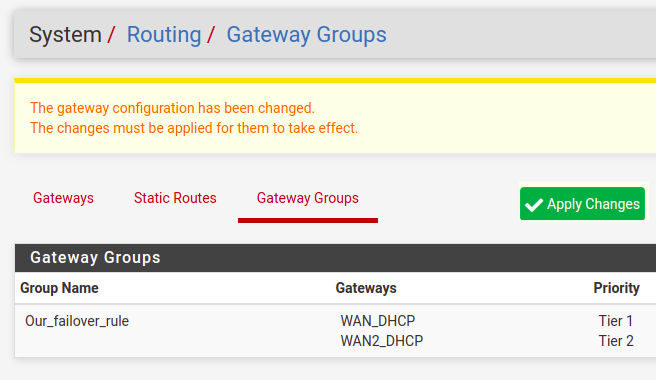
In the figure below, we can verify that the gateway group has been created. Now, let’s click on ”Apply Changes” for the changes to take effect.
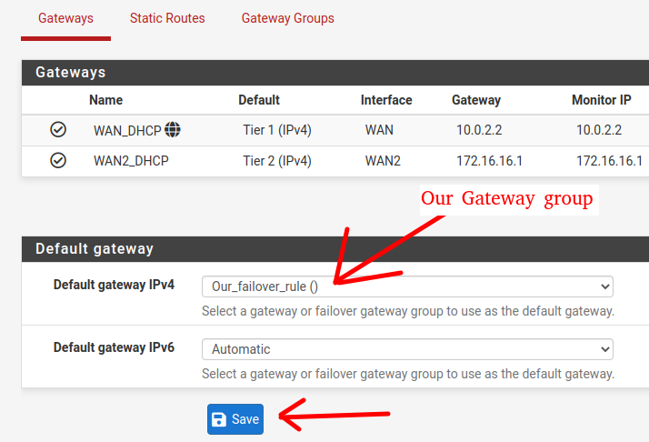
In the figure below, we can see that the first WAN (WAN_DHCP) is the main gateway.
Now, let’s change the Default IPv4 gateway field to the gateway group we created. In our case the group has the name “Our_failover_rule”.
After that, we will click on “Save”.
Some more pfsense failover settings
Now, let’s go to the “System->Advanced->Miscellaneous” page.
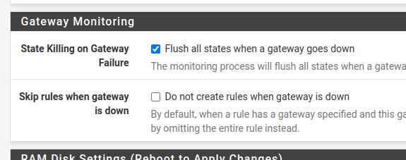
Next, we will search for “gateway Monitoring” and we will select the option “Flush all states when a gateway goes down” within “State Killing on Gateway Failure”. Then go to the bottom of the page and click on “Save”.
The “Flush all states when the gateway goes down” option allows resetting the states of connections that were using the failed gateway. This way, it allows new connections to be made using the new gateway you took over.
There is another option within Skip rules when gateway is down is “Do not create rules when gateway is down”. By enabling this option, rules specific to a gateway will be disregarded when the gateway is disabled. This may make sense in some cases and will depend on your business scenario. In this tutorial we will not enable this option.
Testing pfsense failover
Now let’s test failover. For this, we will use the traceroute command inside pfsense. In this way, using the traceroute command we will be able to check the output path, that is, the output gateway.
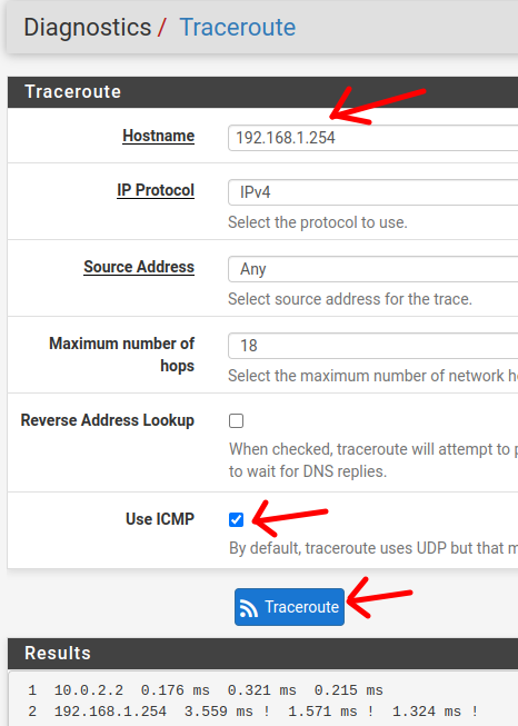
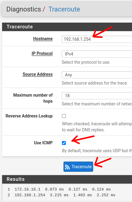
To run the tests, go to the “Diagnostics/Traceroute” page. Next, let’s enter an IP to monitor the output. In our case we entered the IP of our last Internet router. However, we could do the procedure using some public IP as well.
Let’s enable the “Use ICMP” option to perform the test faster. And then click on “Traceroute”.
We can verify that the first hop is the IP “10.0.2.2”, this IP is used in the connection of the first WAN with the virtualbox network. This way, we can verify that the egress is using the first WAN as the main gateway.
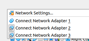
Now let’s go into the virtual machine and disconnect the first WAN interface.

When clicking on “Adapter 1 “, the network adapter will be disconnected.
Now let’s go back to the “System/Routing/Gateway” page. On this page, we can verify that the main gateway is now “WAN 2” and that it has the IP “172.16.16.1”.
Now, let’s test the output with traceroute. To do this, we will access the “Diagnostics/Traceroute” page. Next we will enter an outgoing IP and we will check the result.
Now we can see in the figure below that the output is using the gateway “172.16.16.1”. This is the interface IP of our second “WAN 2” gateway. In this way, we can verify that the failover is occurring correctly.
Tutorial Load Balance + Failover
Part 01: Configure Failover in PfSense
Part 02: Configure Load Balance with PfSense
See Also :
Snort PfSense : Detect DoS Attack
Turn the raspberry pi into a WIFI router
SquidGuard: how to import blocklist?
Arpwatch: Installation and Configuration

Juliana Mascarenhas
Data Scientist and Master in Computer Modeling by LNCC.
Computer Engineer