If you are taking your first steps in learning computer networks, understanding the Client-Server relationship is fundamental. In the real world, every time you type a website into your browser, your computer makes an HTTP request to a remote web server.
In this practical tutorial, we will simulate exactly this process inside Cisco Packet Tracer. We will connect a PC directly to a Web Server in the same subnet, configure the IP addresses, perform connectivity tests, and access a customized HTML page directly through the simulated PC’s browser.
The Laboratory Scenario
For this simple and straightforward guide, we will use:
- Local Network (LAN): 192.168.0.0/24
- Client Device (PC): IP 192.168.0.2 | Mask 255.255.255.0
- Web Server (HTTP): IP 192.168.0.10 | Mask 255.255.255.0
- Physical connection medium: Crossover Cable (Copper Crossover)
💡 Expert Tip: Since we are connecting two devices of the same category (both are “hosts/end devices”), we must necessarily use a Crossover Cable (Copper Crossover) in Packet Tracer so that the network cards can transmit and receive data directly. If you use the straight-through cable (Straight-Through), the physical connection will have red lights (disconnected).
Step 1: Building the Physical Topology
Open Cisco Packet Tracer. In the end devices tab (End Devices), add 1 PC and 1 Server to your workspace.
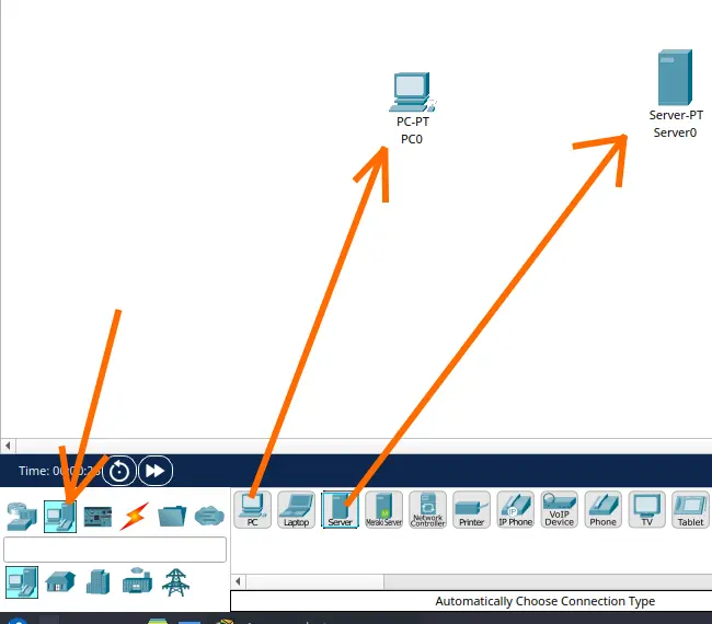
In the connections tab (lightning bolt icon / Connections), select the black dashed cable, which represents the copper crossover cable (Copper Cross-Over).
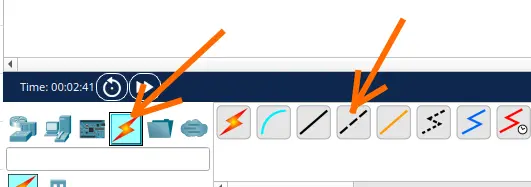
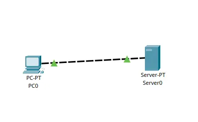
Connect the cable to the FastEthernet0 interface of the PC and to the FastEthernet0 interface of the Server.
The connection lights on both sides should turn green immediately.
Step 2: Configuring the Computer’s IP (Client)
Now let’s configure the logical address on our client PC:
- Click on the PC to open the properties window.
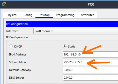
- Go to the Desktop tab and click on IP Configuration.
- Configure the following parameters:
- IP Address: 192.168.0.10
- Subnet Mask: 255.255.255.0
- (Optional) Default Gateway: You can leave it blank, because since the devices are on the same physical and logical network, they do not need a router to communicate.
Step 3: Configuring the IP and Web Service on the Server
1. Server IP Configuration
- Click on the Server to open its properties.
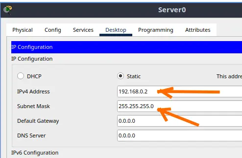
- Go to the Desktop > IP Configuration tab.
- Fill in the data:
- IP Address: 192.168.0.2
- Subnet Mask: 255.255.255.0
2. Customizing the Web Page (Optional, but very cool!)
Packet Tracer already comes with the HTTP/HTTPS service active by default on the server, but we can customize the page to prove that we were the ones who configured it.
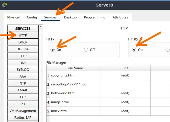
Inside the Server properties, go to the Services tab. On the left side menu, make sure the HTTP option is selected.
Verify if the HTTP and HTTPS services are marked as On.
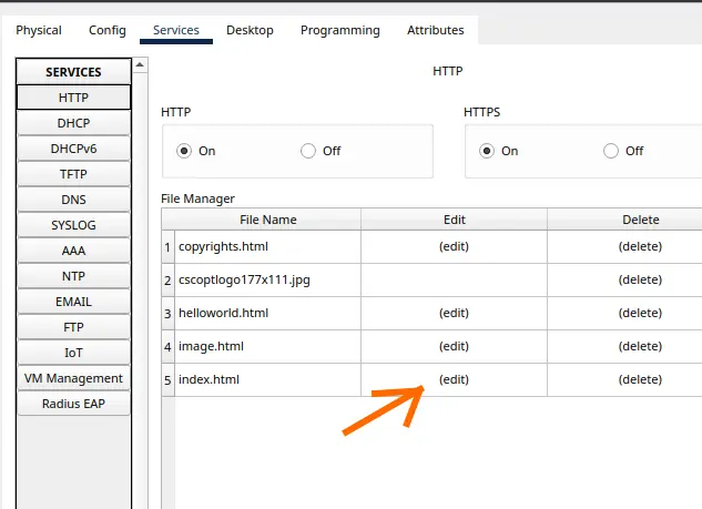
Locate the index.html file in the list and click on Edit.
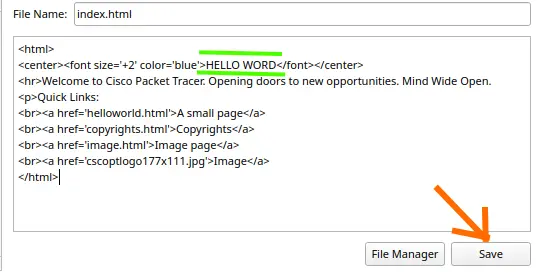
Change the default text inside the HTML tags (for example, change the title from “Cisco Packet Tracer” to “Hello World”).
Click on Save and confirm the replacement.
Step 4: Testing Connectivity (The Ping)
Before opening the browser, we need to ensure that the cables and IPs are communicating perfectly. We will test this through the ICMP protocol (Ping).
- Open the PC properties.
- Go to Desktop and click on Command Prompt.
- Type the following command and press Enter:
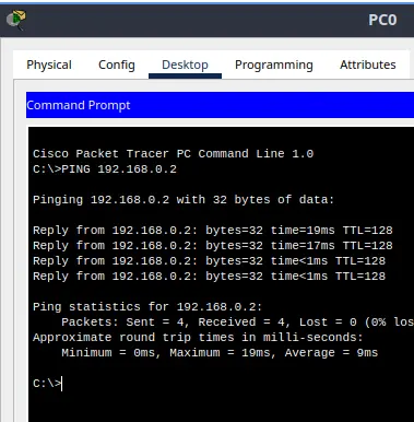
ping 192.168.0.2
If everything is correct, you will see the server’s responses confirming end-to-end connectivity:
Step 5: Accessing the Web Server via Browser
With the physical and logical connectivity tested, it is time to make our real HTTP request!
On the PC, go to the Desktop tab and open the Web Browser.
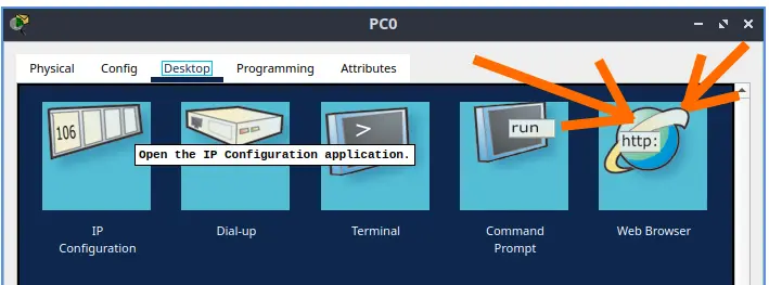
In the URL field, type the IP address of our server: http://192.168.0.2 (or just 192.168.0.2) and click the Go button.
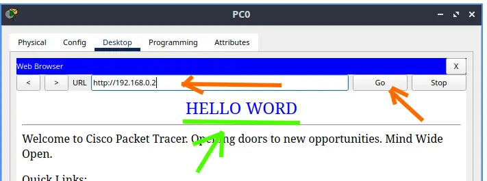
The browser will load the web page hosted on the server, displaying the text you customized in Step 3!
Frequently Asked Questions and Common Student Errors (FAQ)
1. Why did my cable lights turn red?
Generally, this happens because you used the straight-through cable (Copper Straight-Through) instead of the crossover cable (Copper Crossover). Remember: Devices on the same layer (PC and Server) require crossover cables when connected directly without a switch in between.
2. The ping failed with “Request timed out”. What could it be?
Verify if the IPs were entered correctly on both devices and if they belong to the same range (e.g., 192.168.0.2 and 192.168.0.10 with a 255.255.255.0 mask). Also make sure that the correct cable was used.
3. Do I need to configure the Default Gateway in this lab?
No. Since the traffic does not need to go out to an external network (another subnet), the hosts can communicate using only the local network address. The Gateway is only mandatory when packets need to pass through a router.
Lab 1: Install Packet Tracer on Linux
Lab 2: Packet Tracer for Dummies: Setting Up Your First Network with 2 PCs (Quick Start Guide)
Lab 3: How to Create a Network with a Switch in Packet Tracer – Step-by-Step Guide for Beginners
Lab 4: Packet Tracer network with one router
Lab 5: Configure DHCP in Packet Tracer: Server & Router Guide
Lab 6: How to Configure NAT in Packet Tracer (Step-by-Step)
Lab 7: Tutorial: Web Server in Packet Tracer (Client-Server)
Lab 8: Tutorial: Using Port Forwarding in Packet Tracer

Juliana Mascarenhas
Data Scientist and Master in Computer Modeling by LNCC.
Computer Engineer