In the real world, companies and homes use only one public IP address (provided by the internet service provider) for two essential purposes:
- Allow multiple internal computers to access external websites on the internet (NAT Overload/PAT).
- Allow external clients to access specific application servers within the local network (Port Forwarding).
If you want to learn how these two concepts coexist and work independently on the same equipment, this practical guide is for you. We will configure a hybrid scenario from scratch in Cisco Packet Tracer using the ISR 2911 enterprise router.
The Laboratory Scenario
For this ultimate lab, we will integrate multiple components into a single network topology:
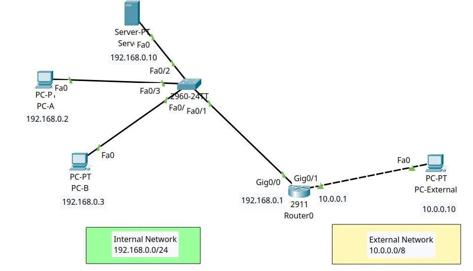
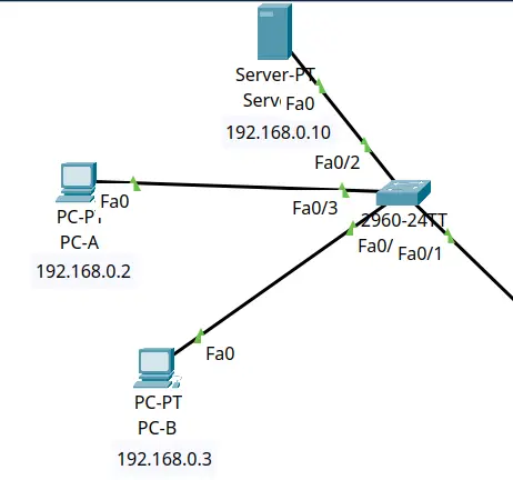
Internal Network (LAN): Private subnet 192.168.0.0/24
- PC-A (Internal Client): IP 192.168.0.2 | Gateway: 192.168.0.1
- PC-B (Internal Client): IP 192.168.0.3 | Gateway: 192.168.0.1
- Web Server (HTTP): IP 192.168.0.10 (Real port: 80) | Gateway: 192.168.0.1
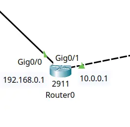
Router (Edge/NAT): Cisco ISR 2911
- LAN Interface (Inside):
GigabitEthernet0/0– IP 192.168.0.1 - WAN Interface (Outside):
GigabitEthernet0/1– IP 10.0.0.1
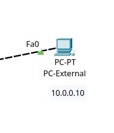
External Network (WAN/Simulated Internet): Public subnet 10.0.0.0/8
- External PC (Internet): IP 10.0.0.10 | Gateway: 10.0.0.1
Attention to the Router Model (Very Important!): Use specifically the Cisco ISR 2911 router in Packet Tracer. Older models like the 1841 use
FastEthernet0/0ports, while newer models like the 4331 use three digits (GigabitEthernet0/0/0). The 2911 model ensures that you can copy and paste our interface commands (GigabitEthernet0/0andGigabitEthernet0/1) directly into the console without syntax errors.
Our Practical Objectives:
- Make PC-A and PC-B able to browse and ping the External PC using NAT Overload (PAT).
- Make the External PC able to open the Internal Web Server page by typing
http://10.0.0.1:8080(using Port Forwarding).
Step 1: Basic IP Configuration on Devices
Open the IP configuration of each host in the simulator and apply the following parameters:
1. Internal PCs (PC-A and PC-B)
- PC-A: IP 192.168.0.2 | Mask: 255.255.255.0 | Gateway: 192.168.0.1
- PC-B: IP 192.168.0.3 | Mask: 255.255.255.0 | Gateway: 192.168.0.1
2. Internal Web Server
- Server: IP $192.168.0.10$ | Mask: 255.255.255.0 | Gateway: 192.168.0.1
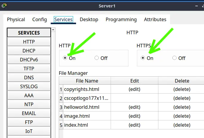
- (Make sure the HTTP service is turned on under “Services” > “HTTP” > “On” )
3. External PC
- External PC: IP 10.0.0.10 | Mask: 255.0.0.0 | Gateway: 10.0.0.1
Expert Note: The Default Gateway pointing to the respective router interfaces is mandatory on all devices ( Excluding the External PC because this PC will only see the router’s external interface).
Step 2: Configuring the Interfaces and NAT Domain on the Router
Access the Router terminal to define the NAT domains (Inside and Outside):
Let’s enable the configuration terminal.
Router> enable
Router# configure terminal
Next, we will configure the Interface facing the LAN (Inside).
Router (config)# interface GigabitEthernet0/0
Router (config-if)# ip address 192.168.0.1 255.255.255.0
Router (config-if)# ip nat inside
Router (config-if)# no shutdown
Router (config-if)# exit
Then, we will configure the Interface facing the WAN/Internet (Outside)
Router (config)# interface GigabitEthernet0/1
Router (config-if)# ip address 10.0.0.1 255.0.0.0
Router (config-if)# ip nat outside
Router (config-if)# no shutdown
Router (config-if)# exit
Step 3: Configuring NAT Overload (PAT) for Internal Browsing
To allow PC-A and PC-B to browse the external network by sharing the public IP of the GigabitEthernet0/1 interface, we need two things:
An Access Control List (ACL) to select who belongs to our private network. To do this, we create the ACL below allowing only our private subnet
router (config)# access-list 1 permit 192.168.0.0 0.0.0.255
The activation of translation mapping with the overload keyword. To do this, we enable dynamic NAT associated with the outbound interface (PAT)
router (config)# ip nat inside source list 1 interface GigabitEthernet0/1 overload
Step 4: Configuring Port Forwarding for the Web Server
With the internal computers now able to go out to the network, let’s configure the inbound traffic. We want any request coming from the internet on the public port 8080 to be redirected to port 80 of our local web server.
Since this rule maps exactly to a single port, we do not need an ACL. Type the command below:
router (config)# ip nat inside source static tcp 192.168.0.10 80 10.0.0.1 8080

Step 5: Testing the Complete Solution
Now let’s perform the two tests that prove the settings are coexisting without conflicts.
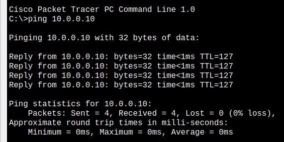
Test 1: Testing Outbound (NAT Overload)
- Open the command prompt (Command Prompt) on PC-A (192.168.0.2).
- Type the command
ping 10.0.0.10and press Enter (this is the external PC’s IP). - Repeat the same test from PC-B.
- Both connections should respond successfully.
Test 2: Testing Inbound (Port Forwarding)
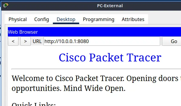
- Open the web browser (Web Browser) on the External PC (10.0.0.10).
- In the address (URL) field, type
http://10.0.0.1:8080and click Go. - The browser should render the website hosted on your internal server perfectly!
Verifying Active Translations in the CLI
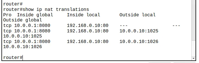
To check how the translations behave, type in the router’s privileged mode:
router# show ip nat translations
The result will show the static Port Forwarding entry and the dynamic Overload port translations temporarily created by the internal PCs’ pings:
Complete Configuration CLI Script
Copy the script below and use the Paste button in Packet Tracer on your 2911 Router’s CLI to configure the scenario quickly:
enable
configure terminal
interface GigabitEthernet0/0
 ip address 192.168.0.1 255.255.255.0
 ip nat inside
 no shutdown
exit
interface GigabitEthernet0/1
 ip address 10.0.0.1 255.0.0.0
 ip nat outside
 no shutdown
exit
access-list 1 permit 192.168.0.0 0.0.0.255
ip nat inside source list 1 interface GigabitEthernet0/1 overload
ip nat inside source static tcp 192.168.0.10 80 10.0.0.1 8080
end
write memory
Frequently Asked Questions (FAQ)
1. Why do we need an ACL for NAT Overload, but not for Port Forwarding?
NAT Overload needs to translate multiple computers dynamically. It uses the ACL as an “allow list” to know which range of private IPs has the right to browse. Port Forwarding is an individual static mapping done for a single port on a single IP, which means the router already knows exactly what to do with the packet without needing a selection list.
2. Why can PC-A ping the External PC without its outbound port being mapped first?
Because the router creates a temporary dynamic translation table automatically as soon as PC-A initiates the connection from the inside out. The router registers that the response to the returning packet must be sent to PC-A’s private IP.
3. Can I use hybrid rules on the same public IP?
Yes, this is the default behavior of a residential router (like the one you have at home). It creates dozens of dynamic outbound sessions for cell phones and computers to browse while redirecting static inbound ports to IP cameras or video game consoles without any conflict.
Did you like this integrated lab? Let us know in the comments if your server responded perfectly to the external test!
Lab 1: Install Packet Tracer on Linux
Lab 2: Packet Tracer for Dummies: Setting Up Your First Network with 2 PCs (Quick Start Guide)
Lab 3: How to Create a Network with a Switch in Packet Tracer – Step-by-Step Guide for Beginners
Lab 4: Packet Tracer network with one router
Lab 5: Configure DHCP in Packet Tracer: Server & Router Guide
Lab 6: How to Configure NAT in Packet Tracer (Step-by-Step)
Lab 7: Tutorial: Web Server in Packet Tracer (Client-Server)
Lab 8: Tutorial: Using Port Forwarding in Packet Tracer

Juliana Mascarenhas
Data Scientist and Master in Computer Modeling by LNCC.
Computer Engineer