If you have already learned how to create a local network and configure a basic router, you know that computers on the same network talk using a Switch, and that the Router is the gateway out of your local network.
But what happens when we need to connect two physically distant local networks, such as a company’s Headquarters and Branch?
In the real world, routers don’t guess where to send data. They need a “roadmap,” known as a Routing Table. In this tutorial, you will learn how to build this map manually using Static Routing and test the communication between networks using only the ping command.
The Lab Scenario
We will interconnect two distinct local area networks (LANs) through a dedicated communication link (WAN):
- Headquarters Network (LAN 1): IP Range
192.168.1.0/24 - Interconnection Link (WAN): IP Range
10.0.0.0/30 - Branch Network (LAN 2): IP Range
192.168.2.0/24
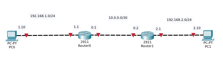
Addressing Table
| Device | Interface | IP Address | Subnet Mask | Default Gateway |
| PC-Headquarters | FastEthernet0 | 192.168.1.10 | 255.255.255.0 | 192.168.1.1 |
| Router-Headquarters (R1) | Gig0/0 (LAN) | 192.168.1.1 | 255.255.255.0 | N/A |
| Router-Headquarters (R1) | Gig0/1 (WAN) | 10.0.0.1 | 255.255.255.252 | N/A |
| Router-Branch (R2) | Gig0/1 (WAN) | 10.0.0.2 | 255.255.255.252 | N/A |
| Router-Branch (R2) | Gig0/0 (LAN) | 192.168.2.1 | 255.255.255.0 | N/A |
| PC-Branch | FastEthernet0 | 192.168.2.10 | 255.255.255.0 | 192.168.2.1 |
Configuration Step-by-Step
Step 1: Building the Topology in Packet Tracer
- Insert 2 Routers (recommended models:
2911orISR4321). - Insert 2 PCs (PC-Headquarters and PC-Branch).
- Connect the devices according to the table above.
- Attention: To interconnect the
GigabitEthernet0/1ports of the two routers, use a Crossover (Copper Cross-Over) cable.
- Attention: To interconnect the
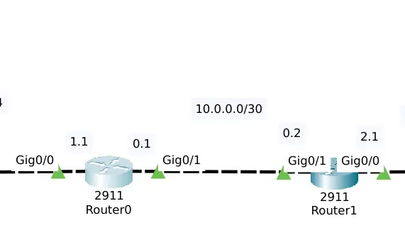
Step 2: Configuring the PCs (Headquarters and Branch)
Click on PC-Headquarters, go to Desktop -> IP Configuration and set:
- IP Address:
192.168.1.10 - Subnet Mask:
255.255.255.0 - Default Gateway:
192.168.1.1
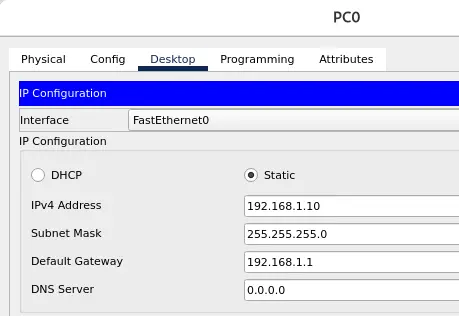
Click on PC-Branch, go to Desktop -> IP Configuration and set:
- IP Address:
192.168.2.10 - Subnet Mask:
255.255.255.0 - Default Gateway:
192.168.2.1
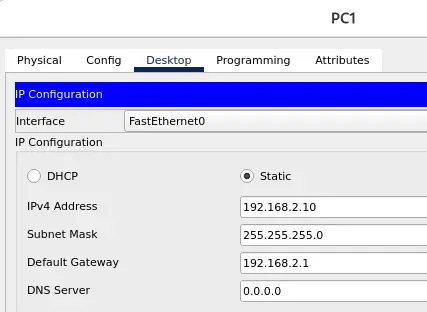
Step 3: Configuring Router Interfaces via CLI
Open the CLI tab of the Router-Headquarters (R1) and type the commands below to name the equipment, activate and address the ports:
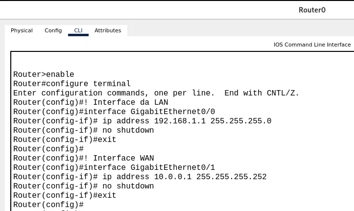
enable
configure terminal
! Interface da LAN
interface GigabitEthernet0/0
 ip address 192.168.1.1 255.255.255.0
 no shutdown
exit

! Interface WAN
interface GigabitEthernet0/1
 ip address 10.0.0.1 255.255.255.252
 no shutdown
exit
Now, open the CLI tab of the Router-Branch (R2) and do the equivalent configuration:
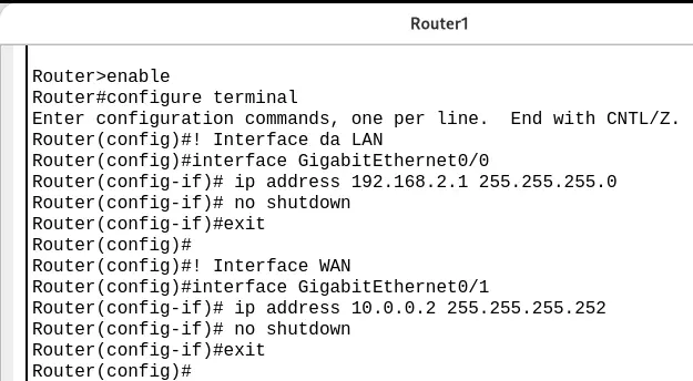
enable
configure terminal
! Interface da LAN
interface GigabitEthernet0/0
 ip address 192.168.2.1 255.255.255.0
 no shutdown
exit

! Interface WAN
interface GigabitEthernet0/1
 ip address 10.0.0.2 255.255.255.252
 no shutdown
exit
The Verification Moment: Why Does the Ping Fail?
If you open the Command Prompt on PC-Headquarters now and try to ping 192.168.2.10 (PC-Branch), the response will be Request timed out.
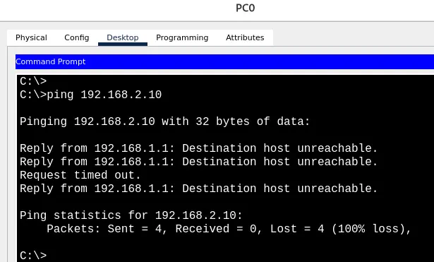
Understanding the Theory:
The Router-Headquarters only knows the networks directly connected to it (
192.168.1.0and10.0.0.0). It does not know that the192.168.2.0network exists. When a packet for this unknown network arrives at the router, it simply drops it. We need to teach it the way!
Step 4: Configuring Static Routes (ip route)
The syntax to create a static route in Cisco IOS is:
ip route [Destination_Network] [Destination_Mask] [Next_Hop_IP]
On the Router-Headquarters (R1), inform that to reach the Branch network (192.168.2.0), the packet must be sent to the Router-Branch IP (10.0.0.2):

enable
configure terminal
ip route 192.168.2.0 255.255.255.0 10.0.0.2
The Golden Rule of Networking: Communication is a two-way street!
It’s not enough for the packet to reach the Branch; the Router-Branch needs to know how to return the response to the Headquarters (192.168.1.0).
Configure the return route on the Router-Branch (R2):

enable
configure terminal
ip route 192.168.1.0 255.255.255.0 10.0.0.1
Testing Connectivity
- Open the Command Prompt of the PC-Headquarters.
- Type the command:Bash
ping 192.168.2.10
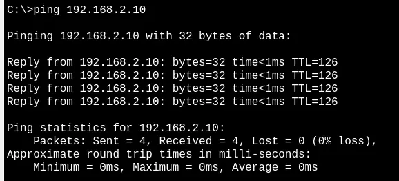
(Note: It is common for the first packet to fail due to the ARP protocol resolution process. Subsequent packets should return success with Reply from 192.168.2.10!)
To view the packet path crossing the two routers in real time, switch Packet Tracer from Realtime mode to Simulation mode, trigger the ping again and click Play.
Complete Configuration Script (For Debugging)
If for some reason your test did not work, use the scripts below to compare with your configurations or paste directly into the routers’ terminal in configure terminal mode.
Router-Headquarters (R1)
enable
configure terminal
interface GigabitEthernet0/0
 ip address 192.168.1.1 255.255.255.0
 no shutdown
exit

interface GigabitEthernet0/1
 ip address 10.0.0.1 255.255.255.252
 no shutdown
exit

! Static route indicating how to get to the branch office
ip route 192.168.2.0 255.255.255.0 10.0.0.2

end
write memory
Router-Branch (R2)
enable
configure terminal
interface GigabitEthernet0/0
 ip address 192.168.2.1 255.255.255.0
 no shutdown
exit

interface GigabitEthernet0/1
 ip address 10.0.0.2 255.255.255.252
 no shutdown
exit

! Static return route indicating how to reach the headquarters
ip route 192.168.1.0 255.255.255.0 10.0.0.1

end
write memory
Useful Diagnostic Commands (Troubleshooting)
If you need to validate your configuration via the terminal, use these two commands in enable mode:
show ip interface brief: Verifies if the ports have the statusup / up. Ifadministratively downappears, it means theno shutdowncommand is missing on the interface.
show ip interface brief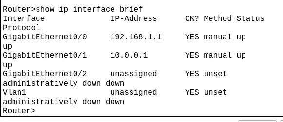
show ip route: Displays the routing table. Look for the line starting with the letterS(for Static), confirming that the manual route was inserted successfully.
show ip route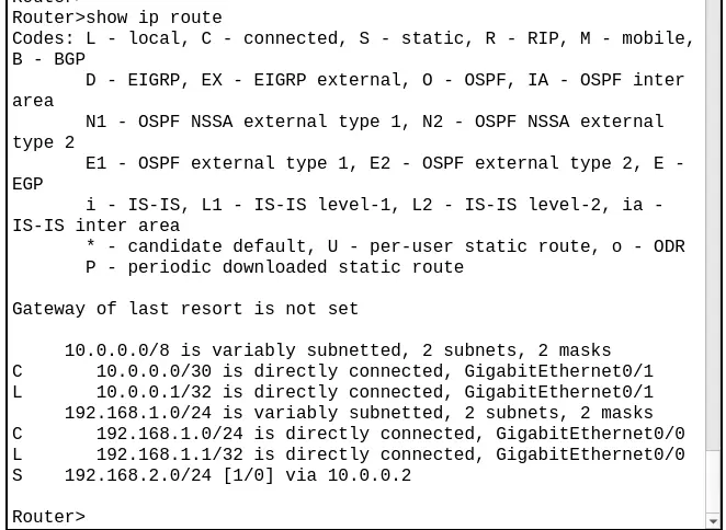
Lab 1: Install Packet Tracer on Linux
Lab 2: Packet Tracer for Dummies: Setting Up Your First Network with 2 PCs (Quick Start Guide)
Lab 3: How to Create a Network with a Switch in Packet Tracer – Step-by-Step Guide for Beginners
Lab 4: Packet Tracer network with one router
Lab 5: Static Routing in Packet Tracer: Connecting 2 Networks
Lab 6: Configure DHCP in Packet Tracer: Server & Router Guide
Lab 7: How to Configure NAT in Packet Tracer (Step-by-Step)
Lab 8: Tutorial: Web Server in Packet Tracer (Client-Server)
Lab 9: Tutorial: Using Port Forwarding in Packet Tracer

Juliana Mascarenhas
Data Scientist and Master in Computer Modeling by LNCC.
Computer Engineer