If you have already followed our practices on RIP and RIPv2, you have seen how routers can learn routes automatically. However, in medium and large enterprise networks, RIP is rarely used due to its limitations (such as the 15-hop limit and the metric based only on hop count).
This is where OSPF (Open Shortest Path First) comes in. It is an open protocol, of the Link-State type, which uses Dijkstra’s algorithm (SPF) to find the fastest path based on bandwidth.
In this practical lab, we will configure OSPF in a simple Single-Area OSPF network and test end-to-end communication with the ping command.
The Topology Scenario
We will use a classic topology of two interconnected blocks:
- LAN 1 (Router 1): Subnet
192.168.10.0/24 - WAN Link (Point-to-Point): Subnet
10.0.0.0/30 - LAN 2 (Router 2): Subnet
192.168.20.0/24
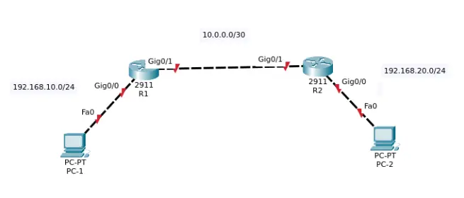
Addressing Table
| Device | Interface | IP Address | Subnet Mask | Default Gateway |
| PC-1 | FastEthernet0 | 192.168.10.10 | 255.255.255.0 | 192.168.10.1 |
| R1 (Router 1) | Gig0/0 (LAN) | 192.168.10.1 | 255.255.255.0 | N/A |
| R1 (Router 1) | Gig0/1 (WAN) | 10.0.0.1 | 255.255.255.252 | N/A |
| R2 (Router 2) | Gig0/1 (WAN) | 10.0.0.2 | 255.255.255.252 | N/A |
| R2 (Router 2) | Gig0/0 (LAN) | 192.168.20.1 | 255.255.255.0 | N/A |
| PC-2 | FastEthernet0 | 192.168.20.10 | 255.255.255.0 | 192.168.20.1 |
Key Concepts Before Configuration
Unlike the simple network command in RIP, the OSPF command requires two essential additional parameters:
1. Process ID (router ospf <process-id>)
The process number (for example, 1 or 10) has only local significance on the router itself. It only serves to identify that instance running in the device’s memory.
2. The Inverted Mask (Wildcard Mask)
Instead of using the normal mask (255.255.255.0), OSPF uses the inverted mask (wildcard).
The mathematical rule to find the wildcard mask is to subtract your subnet mask from the full global mask (255.255.255.255):
- For /24 mask (
255.255.255.0):
255.255.255.255 – 255.255.255.0 = 0.0.0.255 - For /30 mask (
255.255.255.252):
255.255.255.255 – 255.255.255.252 = 0.0.0.3
3. Area 0 (Backbone Area)
OSPF organizes networks into hierarchical areas. In simple networks (with a single area), all routers must necessarily belong to the central area, designated as Area 0 (Backbone).
Configuration Step-by-Step
Step 1: Basic Configuration of Interfaces and PCs
Ensure that the router ports and the computers have the IP addresses from the table assigned and active (no shutdown).
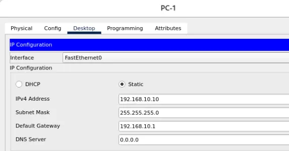
Below we are configuring PC-1 with its IP and pointing to R1’s LAN interface as its Gateway.
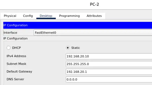
Below we are configuring PC-2 with its IP and pointing to R2’s LAN interface as its Gateway.
Configuring R1’s interfaces.
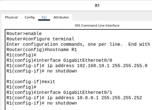
enable
configure terminal
hostname R1

interface GigabitEthernet0/0
ip address 192.168.10.1 255.255.255.0
no shutdown
exit

interface GigabitEthernet0/1
ip address 10.0.0.1 255.255.255.252
no shutdown
exit
Configuring R2’s interfaces.
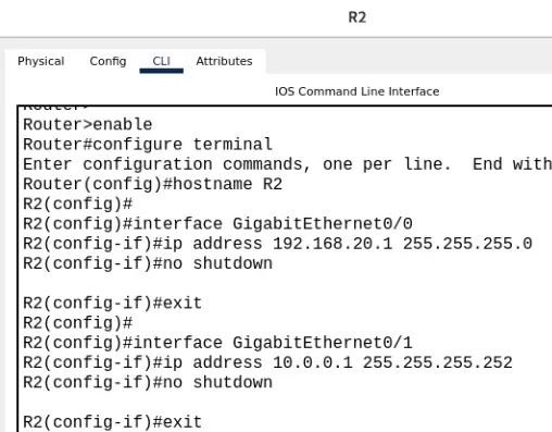
enable
configure terminal
hostname R2

interface GigabitEthernet0/0
ip address 192.168.20.1 255.255.255.0
no shutdown
exit

interface GigabitEthernet0/1
ip address 10.0.0.2 255.255.255.252
no shutdown
exit
Step 2: Activating OSPF on Router 1 (R1)
On the R1 CLI, enter configuration mode and advertise its connected networks (the LAN and the WAN link) inside Area 0:
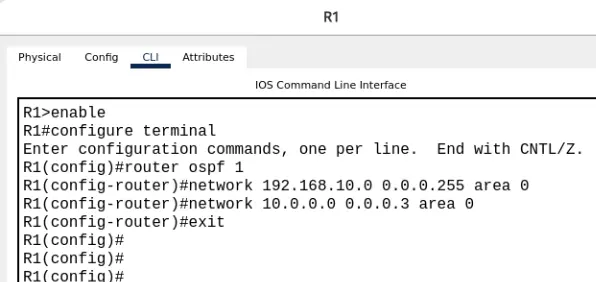
enable
configure terminal
router ospf 1
network 192.168.10.0 0.0.0.255 area 0
network 10.0.0.0 0.0.0.3 area 0
exit
Step 3: Activating OSPF on Router 2 (R2)
On the R2 CLI, execute the equivalent command to advertise its local network and the WAN link:
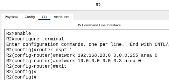
enable
configure terminal
router ospf 1
network 192.168.20.0 0.0.0.255 area 0
network 10.0.0.0 0.0.0.3 area 0
exit
Eye on the Terminal: A few seconds after typing the WAN link command on R2, you will see a system message (Syslog) appear on the screen:
%OSPF-5-ADJCHANGE: Process 1, Nbr 10.0.0.1 on GigabitEthernet0/1 from LOADING to FULL, Loading DoneThis means that R1 and R2 exchanged Hello packets, established adjacency, and synchronized their topological databases!
Audit and Validation Commands (What Changed from RIP?)
Unlike RIP, in OSPF we have direct visibility of the relationship between the devices.
1. Verifying Neighbors
In privileged mode on either of the routers, type:
show ip ospf neighbor
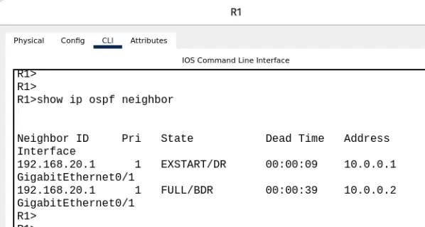
You should see the neighboring router listed with the state FULL/ –. The FULL state confirms that the two routers successfully exchanged their LSAs (Link-State Advertisements).
2. Examining the Routing Table
Type:
show ip route
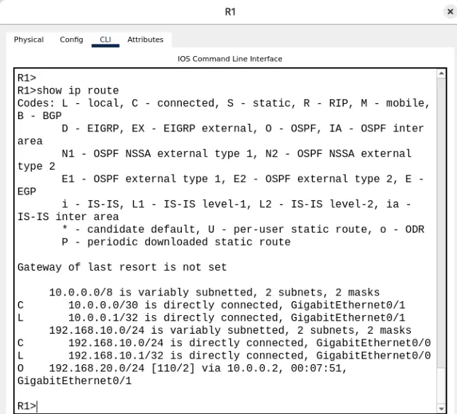
In the routing table, notice the routes marked with the code O (for OSPF):
Plaintext
O 192.168.20.0/24 [110/2] via 10.0.0.2, GigabitEthernet0/1
[110/...]: The value110is the default Administrative Distance (AD) for OSPF (remind students: RIP has an AD of 120 and static routes have an AD of 1).[.../2]: The value2is the cost metric, calculated based on the interface bandwidth, not merely hops.
The Final Connectivity Test
Go to PC-1, open the console (Command Prompt) and test the reachability to PC-2:
ping 192.168.20.10
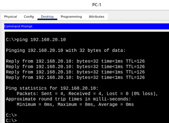
If everything is correct, the replies will start arriving successfully!
Complete Configuration Script (For Debugging)
If any detail didn’t work as expected, use the blocks below to audit your configuration:
Router R1
enable
configure terminal
hostname R1

! --- Interfaces ---
interface GigabitEthernet0/0
 ip address 192.168.10.1 255.255.255.0
 no shutdown
exit

interface GigabitEthernet0/1
 ip address 10.0.0.1 255.255.255.252
 no shutdown
exit

! --- OSPF ---
router ospf 1
 network 192.168.10.0 0.0.0.255 area 0
 network 10.0.0.0 0.0.0.3 area 0
exit

end
write memory
Router R2
enable
configure terminal
hostname R2

! --- Interfaces ---
interface GigabitEthernet0/0
 ip address 192.168.20.1 255.255.255.0
 no shutdown
exit

interface GigabitEthernet0/1
 ip address 10.0.0.2 255.255.255.252
 no shutdown
exit

! --- OSPF ---
router ospf 1
 network 192.168.20.0 0.0.0.255 area 0
 network 10.0.0.0 0.0.0.3 area 0
exit

end
write memory
Next Pedagogical Step
With this foundation consolidated, the students’ next practical challenge can be:
- Explicit Router ID: Teach how to manually assign the
router-idvia Loopback IP addresses. - Passive Interface (
passive-interface): Explain why we should not send OSPF Hello packets unnecessarily into the LAN where only PCs exist.
See more:
Lab 1: Install Packet Tracer on Linux
Lab 2: Packet Tracer for Dummies: Setting Up Your First Network with 2 PCs (Quick Start Guide)
Lab 3: How to Create a Network with a Switch in Packet Tracer – Step-by-Step Guide for Beginners
Lab 4: Packet Tracer network with one router
Lab 5: Static Routing in Packet Tracer: Connecting 2 Networks
Lab 6: Configure DHCP in Packet Tracer: Server & Router Guide
Lab 7: How to Configure OSPF in Packet Tracer (Step-by-Step)
Lab 8: How to Configure NAT in Packet Tracer (Step-by-Step)
Lab 9: Tutorial: Web Server in Packet Tracer (Client-Server)
Lab 10: Tutorial: Using Port Forwarding in Packet Tracer

Juliana Mascarenhas
Data Scientist and Master in Computer Modeling by LNCC.
Computer Engineer