Unlike the link layer, which deals with connections between neighbors, the network layer is responsible for sending packets from source to destination.
When we talk about sending packets between source and destination, a destination can be several hops away from a source. Therefore, between the source and destination machines, we can have several devices responsible for forwarding the packets.
Which equipment to forward packets, is the switch?
No, in this case we are talking about the router.
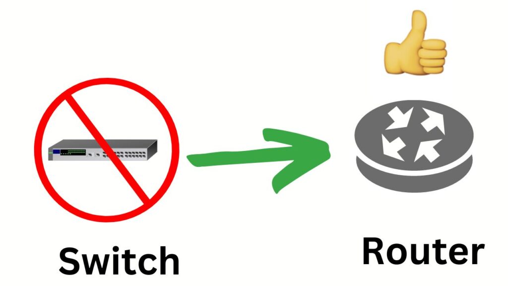
The router is a fundamental piece of equipment in the network layer. This equipment allows us to connect several networks and ensure communication between the networks. That way, when a router receives a packet, it verifies the checksum (if it is IPv4), and checks the destination address to know where to send the packet.
How can the router bridge multiple networks?
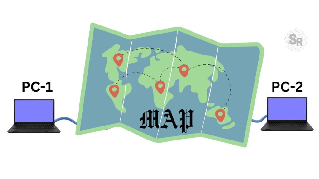
To link multiple networks, the router needs to have a network map. This map is also known as the network topology.
And based on the topology of the network, we can choose the best routes to forward packets between source and destinations.
How does the router know the network map?
We can enter information about the other networks into the router table to let the router know the network map or topology. Moreover, there are two ways to enter this information: manually or automatically.
The way to enter network information manually is when a human administrator enters routes directly into the router.
How to automatically enter network information into the router is left up to the routing protocol. Therefore, the routing protocol is an application that communicates with other routers and shares information about the routing of the routers that make up the network.
Both manual and automatic route configuration are widely used in networks and in some cases we use a combination of both approaches.
What the network layer provides for the transport layer
Must ensure that the services provided to the transport layer are independent of intermediate network equipment such as routers.
In addition, the network layer must handle the topology of the network in a way that is transparent to the transport layer.
The network layer must use a network address numbering protocol regardless of whether it is on a local network or the Internet.
How packet delivery works at the network layer
Scientists argue that routers should limit themselves to transmitting packets between different networks. This behavior leaves the duty of carrying out the error and flow control to the hosts.
This type of network operation is called connectionless, as routers just forward packets end to end.
The other group of scientists argues that the network layer must offer a reliable connection-oriented service and consequently guarantee a quality of service. Thus, in this approach, the network layer should provide flow control and error control.
Currently we have IP which is the main communication protocol between networks and works in a connectionless way. The IP protocol has been working for decades and has evolved from IPv4 to IPv6.
However, some solutions that combine connection orientation have gained space in use, among them we have: MPLS and VLANs.
Connectionless Network Layer
Packages are transmitted without any guarantee or prior configuration. In this way, each packet is routed dependently.
As packets are routed in a dependent way, thinking of a set of packets that go from one source to a destination, some packets can travel through different routes than the others.
This is because, as the packet is routed independently, depending on the configuration of the intermediate router’s route table, the latter may send the packet through different interfaces as the route table changes over time.
Some authors like to call connectionless packets datagrams, this is an allusion to the old telegram system.
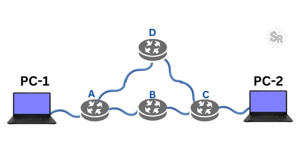
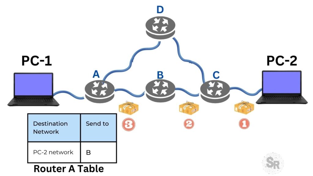
The figure below shows an example of connectionless packet transmission. In this scenario, we have one source computer (PC-1) sending packets to one (PC-2). To send packets, intermediate routers (A,B,C,D) are used.
Note. We are assuming that each router has a route to forward packets to the PC-2 network.
In the first step, the first 4 packets (1,2,3) arriving at Router A destined for PC-2’s network are forwarded to Router B. This forwarding is based on Router A’s route table that has B as the next hop to deliver packets to the PC-2 network.
In the second step, shown in the figure below, the routing algorithm of Router A changes and starts to indicate the path passing through Router D. This change of routes can happen at any time in a router that is using a routing protocol dynamic.
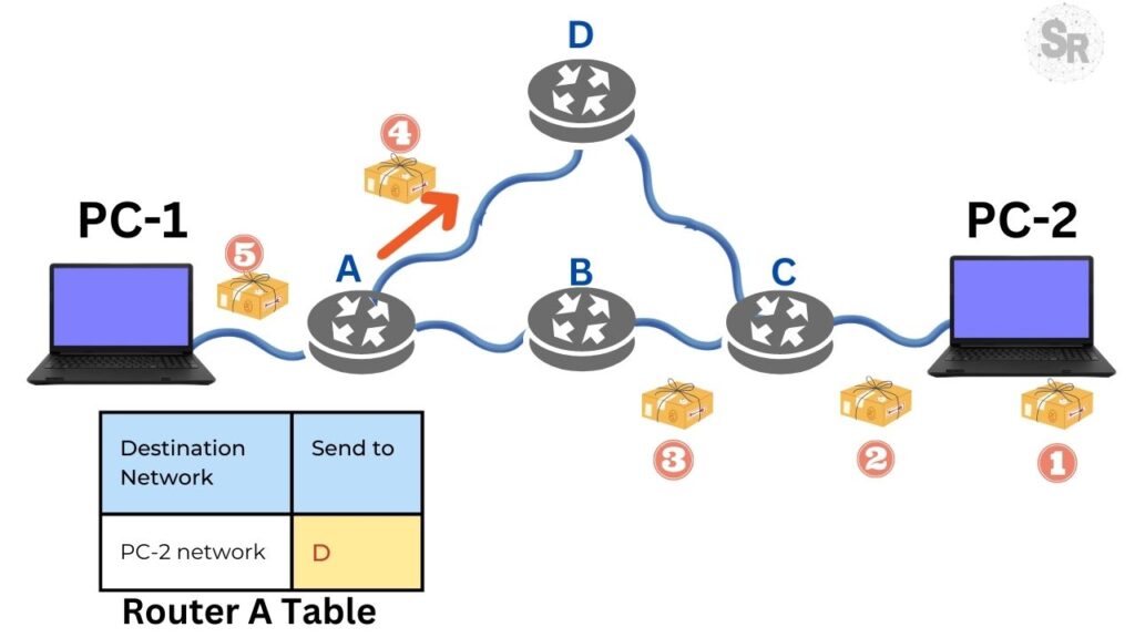
Based on the scenario shown in the two figures above, we can see that part of the packets originating from PC-1 and destined for PC-2 take different routes.
This behavior of packets going through different routes, even being part of the same communication flow. This type of behavior characterizes connectionless communication.
Connection-Oriented Networking Layer
Now let’s understand what the connection-oriented connection would look like. In this case, virtual circuits would be created for data traffic.
The objective of creating virtual circuits is to create a configuration for each data stream so that it is not necessary to choose a route for each packet individually.
Consequently, in the virtual circuit there is the step of creating a connection in which a route between the source and the destination will be chosen.
The information about this route will be stored in the intermediate routers in order to guarantee that all the data of an origin-destination flow pass through the same route.
In order to control the connection status of the virtual circuit, each packet has an identifier that tells which virtual circuit the packet belongs to.
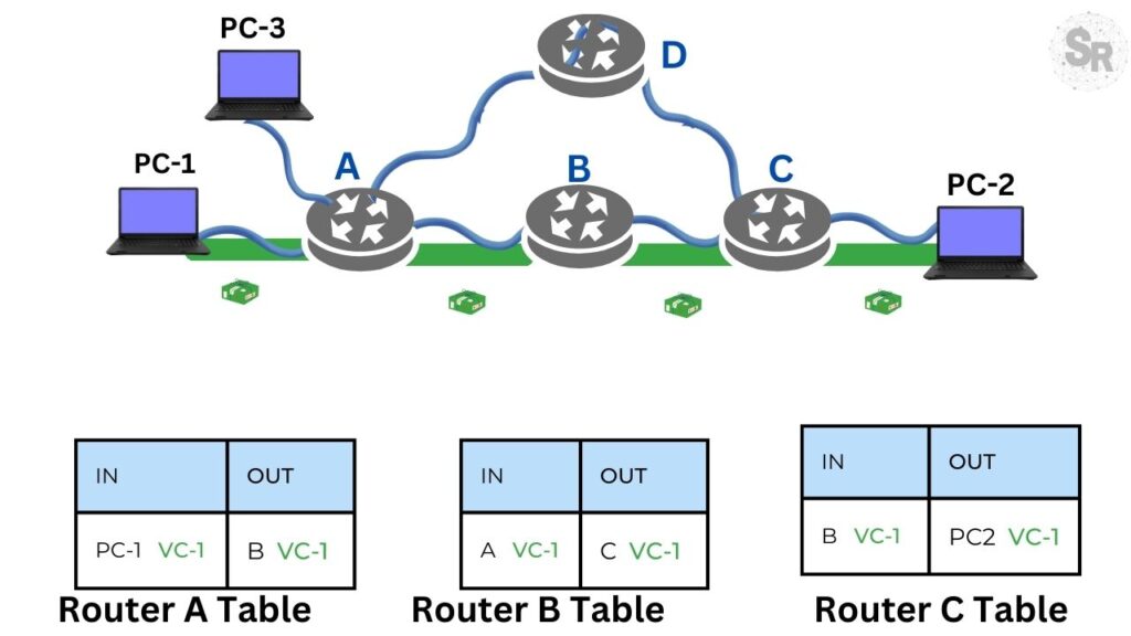
In the figure below, we can see an example of a virtual circuit in operation. In this case, we have a virtual circuit being created between PC-1 and PC-2.
Initially we have the route table of A which indicates that the input (IN) comes from PC-1 and the output (OUT) goes to router B. Furthermore, we can see that the virtual circuit number is 1 ( VC-1 ).
We can see that on the other routers (B,C) the process is repeated using the same VC-1 to mark the packets and forward them with the virtual circuit number VC-1.
Why do we have a number for the circuit in virtual circuits?
This happens because instead of using a destination address such as an IP, the virtual circuit based network uses the circuit number to know where to forward the packet.
Thus, taking the scenario in the figure above, when a packet marked with virtual circuit 1 (VC-1) arrives at A from PC-1, router A knows to forward it to router B.
However , before forwarding it is necessary to know what the marking of the circuit will be before forwarding to B. In this case, the number of circuit will remain the same (VC-1).
In the figure below, let’s assume that a second machine (PC-3) wanted to communicate with PC-2. In this case, a new virtual circuit configuration would be created and for this new configuration we have that between PC-3 and router A we will have virtual circuit number 1 (VC-1) as well.
Notably, Router A receives packets marked with virtual circuit number 1 (VC-1) from PC-1 and PC-3, and one might wonder if this creates some confusion for the router.
The answer is that it does not create confusion for the router, as it knows how to differentiate the entry by the interface that is receiving the packets.
This way, even if the packets leaving PC-1 and PC-3 have virtual circuit number 1 (VC-1) the router knows how to differentiate because one comes from the interface connected to PC-1 and the other comes from the interface connected to PC-2.
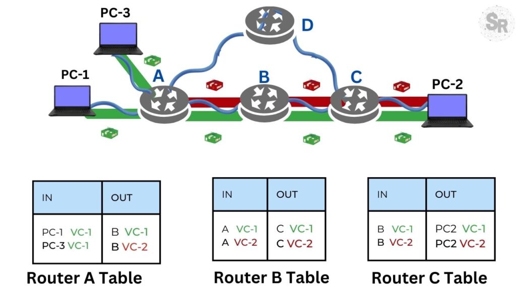
However, as packets coming from PC-3 are forwarded from Router A to Router B, Router B needs to use a different virtual circuit number than VC-1 because between Router A and Router B B VC-1 is already assigned to the virtual circuit creating between PC-1 and PC-2.
This way, the communication between PC-3 and PC-2 will use virtual circuit number 2 between routers A and B. Any other circuit number that is not being used in the table of the two routers could have been chosen.
We can see that we will have to use virtual circuit number 2 also between B and C and also between C and PC-2.
This is because between these nodes virtual circuit 1 is already being used for communication between PC-1 and PC-2.
It is worth mentioning that after using the virtual circuit we have the virtual circuit finalization phase and during this phase the intermediate routers remove the information about the state of the virtual circuit that is being finalized.
Another interesting point when we talk about virtual circuit is the delay for creating the circuit. This is because we have the circuit creation phase that occupies a fraction of the time for the intermediate routers to negotiate the route that the data flow will use.
Consequently, we realized that if we are using virtual circuits for low duration flows, we will have a part of the time destined to the data traffic being consumed by the time used to create the virtual circuit.
Key differences between connection-oriented and connectionless networks
Below is a table with the main differences between connectionless networks and connection-oriented networks.
| Difference | Connection not oriented | Connection oriented |
|---|---|---|
| Need to configure the circuit before sending | No | Yes |
| Addressing type | Destination addressing | Virtual circuit number |
| Need to maintain information about the status of connections | No | Yes |
| Failed router or broken line | The next packets are routed through alternate paths | A new virtual circuit would have to be created again |
| Quality of Service | Difficult task due to the independence in the routing of packages | Easy task, as it could configure the circuit based on the need for quality of service. |
See More:
HTTP Protocol – How Does It Work?

Juliana Mascarenhas
Data Scientist and Master in Computer Modeling by LNCC.
Computer Engineer
Bibliographic reference:
https://learningnetwork.cisco.com/s/article/osi-model-reference-chart
https://www.ietf.org/rfc/rfc1122.txt
Tutorial: Using Port Forwarding in Packet Tracer
Tutorial: Web Server in Packet Tracer (Client-Server)

Email Server & Webmail Setup: Postfix, Dovecot, SnappyMail
Install Ubuntu Server 26 on VirtualBox (Step-by-Step)
How to Configure NAT in Packet Tracer (Step-by-Step)