In this tutorial, we will show you how to configure a network with just one router in Packettracer. It will be a very simple and objective tutorial.
The tutorial will also show some important points such as the use of the default gateway and tests with ping and tracert. In addition, we will show you what the ARP table looks like when one machine is talking to another using a router.
Connecting devices
First, let’s choose the computers we will use in our tutorial. For this, let’s click “End Devices” as we have seen in the tutorial before.
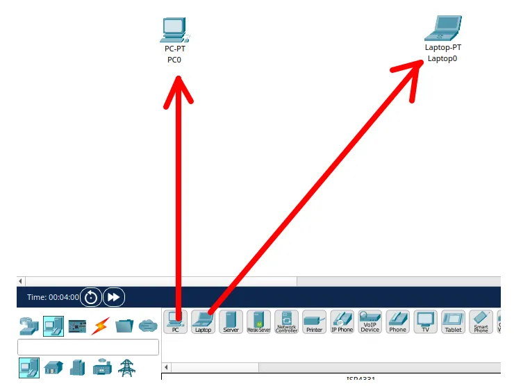
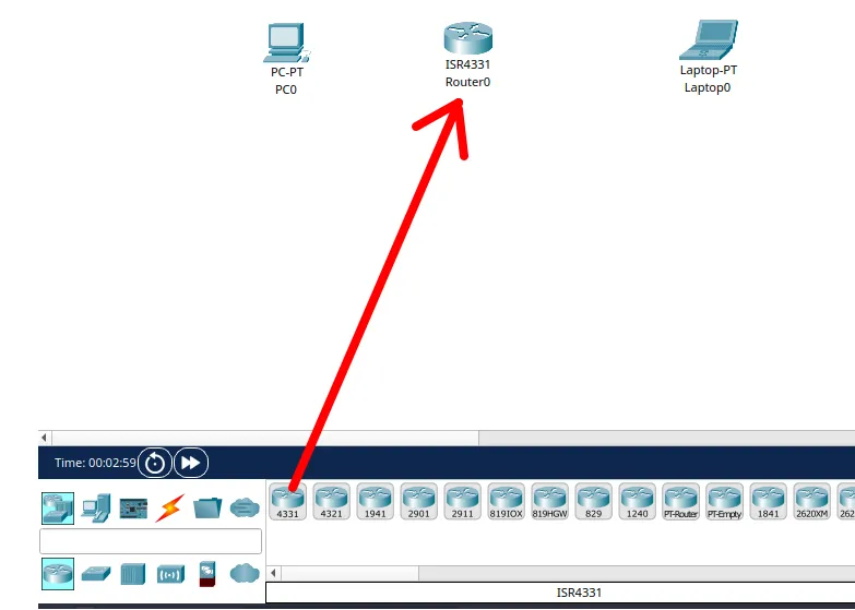
Then we will choose the router by clicking on networking devices and selecting the router.
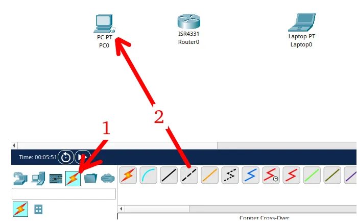
Now, let’s choose the type of connection. As we are connecting equipment that goes at least to the network layer, we will select the “Cross” cable as in the figure below.
Then we will select the Ethernet interface of the first computer.
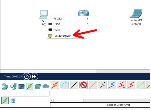
And let’s connect to the router. In this case, we will choose the interface “gigabitenetter0/0/0/0” of the router.
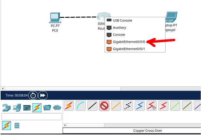
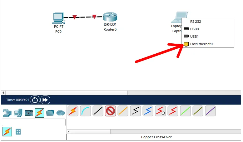
Now, let’s do the same procedure for the other computer by clicking on the “Cross” cable and selecting the computer’s “Fastethernet”.
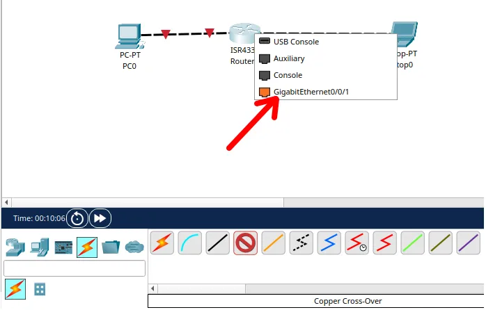
After that, we will select the other “gigabitethernet” interface available on the router. In this case, the available interface is the “gigabitethernet0/0/1”.
We can see that the machines were connected to the router, as shown below.
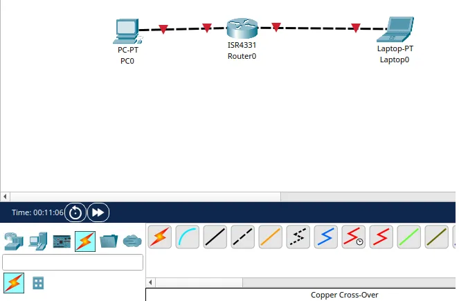
Now we can click on the “text” icon to insert labels with information about the network we are using in each link. I like to do this because it helps me to remember where each network is being used.
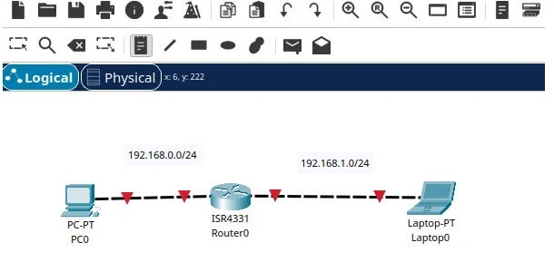
Configuring computers and router
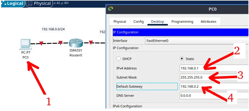
Once you have created the physical connections, let’s start the device configuration. Let’s start with the first computer. In this case, the first computer needs to have an address and mask and also needs to have the “Default Gateway” address.
Remember that the “Default Gateway” is responsible for sending packages that are intended for other networks other than the network that the computer is.
Therefore, in our example the first computer is on the network “192.168.0.0/24” and to talk to any other network it needs to send packages to the “default gateway” which is “192.168.0.2”.
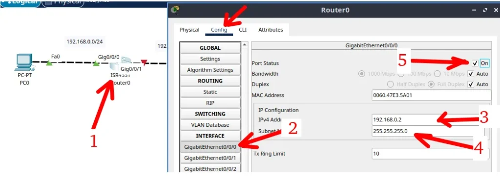
Now let’s double click the router and then click “Config”. Then we will describe the steps for the setting below.
- Step 1: Double click the router.
- Step 2: Select the connected interface to the first computer. In this case it is the “gigabitethernet0/0/0”.
- Step 3: Insert the IP that the router interface will have. Remember that it has to be an IP within the network range that is connected.
- Step 4: Insert the network mask.
- Step 5: Click on “ON” to connect the interface.
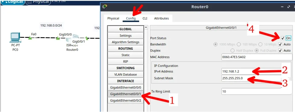
Taking advantage that we are already on the router and we will configure the other interface that is connected to the other network. Let’s describe the steps for the configuration below.
- Step 1: Select the other interface that is connecting the right network. In our case is the “gigabitethernet0/0/1”.
- Step 2: Insert the IP that the router interface will have. Remember that it has to be an IP within the network range that is connected.
- Step 3: Insert the network mask.
- Step 4: Click on “ON” to turn on the interface.
Lastly, let’s set up the other computer and for that we will follow the steps below.
- Double click on the computer.
- Select the “desktop” tab.
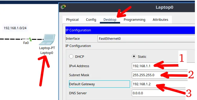
- Step 1: Insert the IP that the computer interface will have. Remember that it has to be an IP within the network range that is connected.
- Step 2: Insert the network mask.
- Step 3: Insert the “Default Gateway” IP. Remember this will be the router interface IP connected to this computer.
Ping Connectivity Test
Once the network is configured, we can start the tests. Let’s start with the connectivity test using the Ping command.
For connectivity testing with the ping command, we will select the left computer and double click. Then we will select the “Desktop” tab and then select the “Command Prompt” as in the figure below.
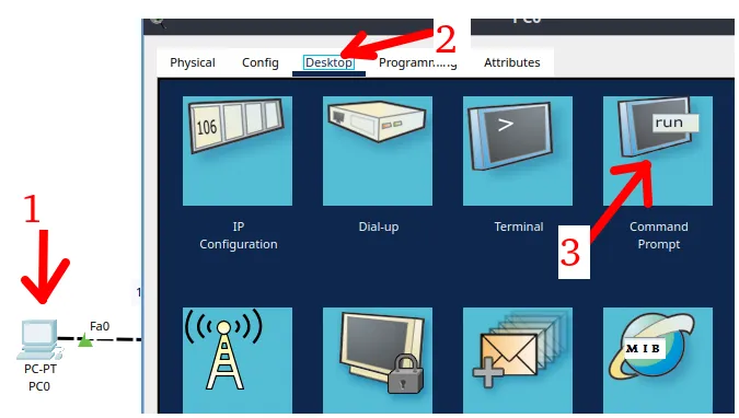
Within the terminal, we will enter the command below to show the IP of the current machine.
ipconfigThen let’s use the ping command and then the destination machine IP. In our case, the destination machine will be the right computer.
ping 192.168.1.1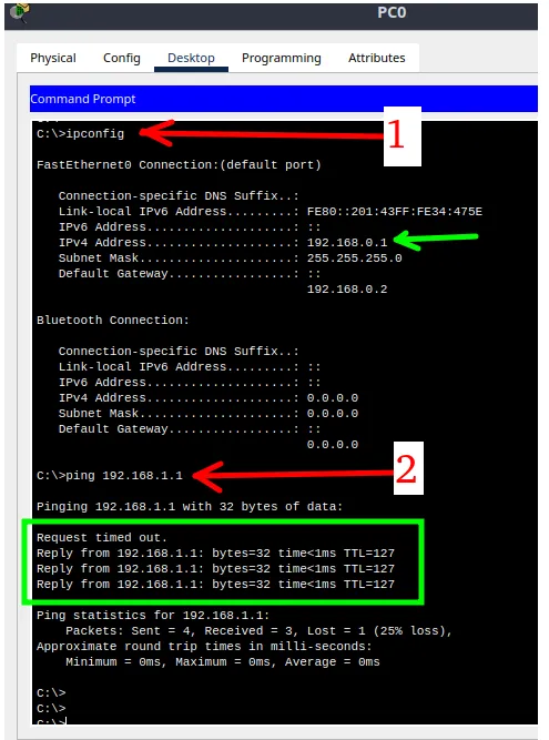
We can see in the figure above that the connectivity test with ping worked correctly.
Now let’s see the heels that exist between the left computer and the right computer. For this, we will use the Tracert command that can be used to know which route the packages are traveling.
Below is the example of the Tracert command for destination 192.168.1.1.
tracert 192.168.1.1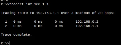
Then we can see the ARP table of the left computer.
arp -aNote that amazing: MAC and IP that appear in the ARP table of the left computer are from the router interface that is connected to the computer itself.

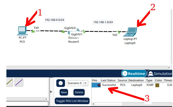
If you want, you can test connectivity using the letter Packet Tracer has. For this you will click the letter as in the figure below.

Then click on the first computer and then click the second computer.
After that you will see a message showing if the connection was successful as in the figure below.
See more:

