
In this practical tutorial, I will show you how to create a simple switch network using the Cisco Packet Tracer simulator, one of the most commonly used tools in network teaching.
If you are taking the first steps in the world of computer networks or need to review essential concepts for certification, this post is for you.
At the end of this guide, you will have configured your first functional network, better understanding the communication between devices and the papers of each component.
In addition to being a great way to learn in practice, this activity helps to consolidate fundamental knowledge about IP addressing, connectivity and operation of switches
Inserting the end devices in the Packet Tracer
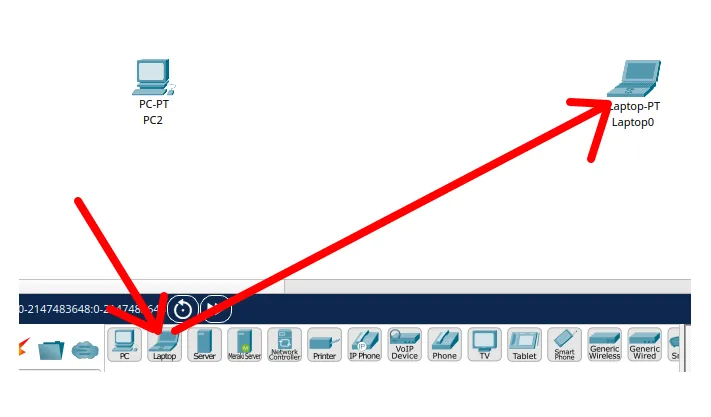
Let’s choose the two computers we will use in our network. For this, let’s go to the lower corner menu and choose “End Devices” or end devices.

After clicking on “End Devices“, let’s choose the device with the name “PC“. O”PC” will be the computer we will use in our network.

Now, let’s click the “PC + Laptop” and drag them to the screen where it will be positioned. After clicking and dragging with the mouse, you can release the mouse button at the location you want to position computers.
Inserting the switch
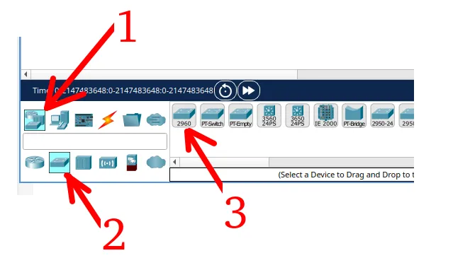
Now, let’s follow the steps of the figure below.
- 1 = Click on “Network Devices
- 2 = Choose the switch.
- 3 = Let’s choose the first switch from the list.
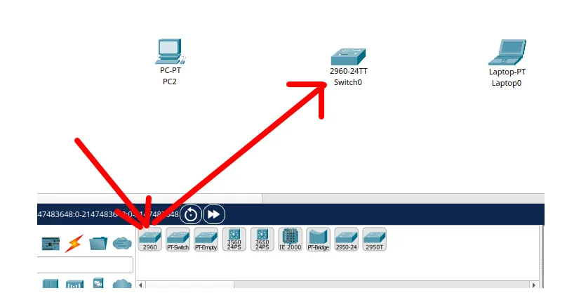
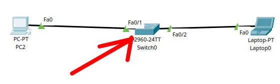
Then let’s drag the switch to the screen and position it between the two computers.
Enabling the labels of the interfaces
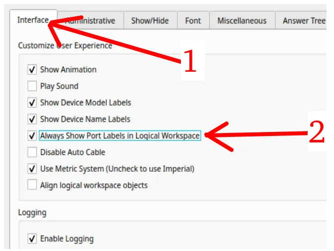
Something interesting when we are using a network with devices is to use the option to see the “labels” of the interfaces. For this, let’s click “Options” and then in “Preference” as in the figure below.
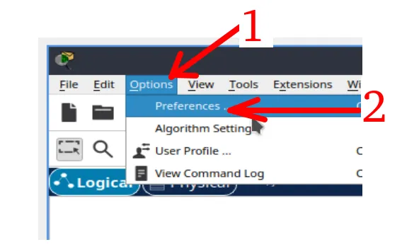
Then let’s click “Interface” and then we will enable the “Always Show Port Labels in Logical Workspace“.
Connecting the devices
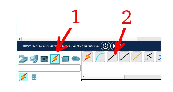
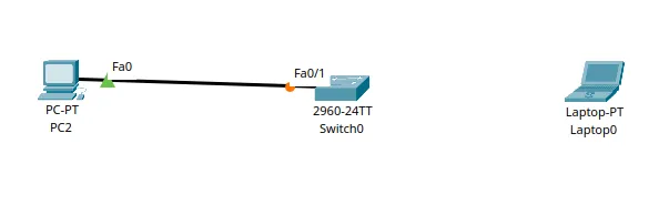
The figure below shows how we will connect the two devices we insert in our network.
For this, let’s click on the radius icon “Connections” represented by arrow 1 and then we will choose the type of cabling as “Copper Straight” represented by arrow 2.
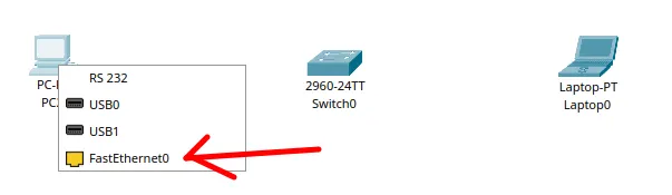
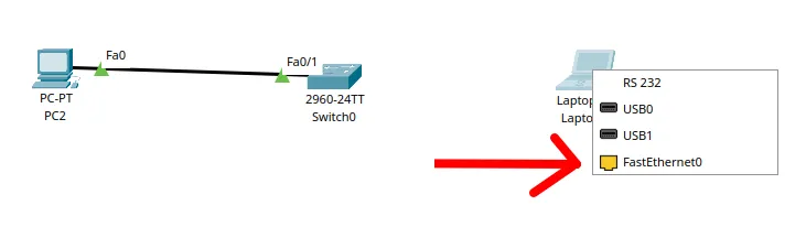
When clicking on the computer after selecting the cable, let’s click “FastEthernet0“as in the figures below.
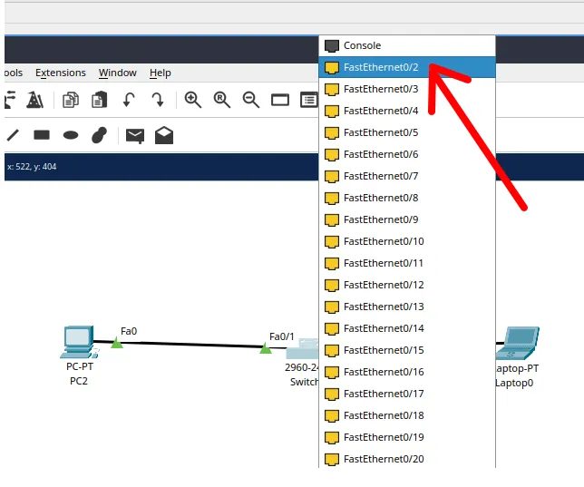
Then let’s click on the switch and choose one of the doors, as in the figure below.
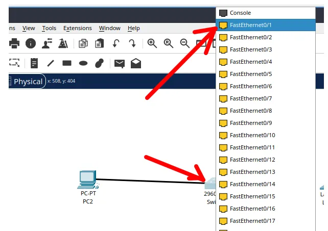
After that we can see that now the first computer is connected to the switch.
Now, let’s connect the second computer to the switch. To do this we will repeat the process we did earlier by clicking the other computer and selecting the interface.
Then we will choose another switch interface to connect the second computer.
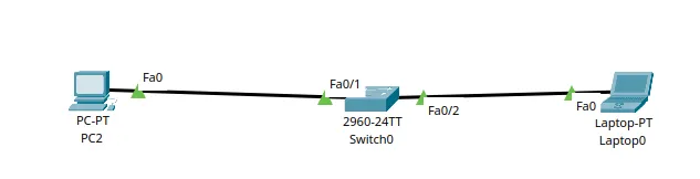
We can see that now the two computers are connected to the switch as in the figure below.
Inserting IP addresses into the devices of Packet Tracer
Now, let’s insert IP addresses into our devices so they can communicate. For this, let’s first choose the first “PC” and let’s double click.
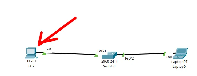
After double clicking on the first “PC”, let’s follow the steps described below and shown in the figure below.
- 1: Let’s click “Config “In the upper menu.
- 2: Let’s choose the device network interface. In this case, it will be “FastEthernet0“.
- 3: Let’s insert the device IP. In this case, it will be “192.168.0.1“.
- 4: Let’s insert the mask of the network. In this case it will be “255.255.255.0“.
- 5: Let’s click the leaving button so that you can leave the configuration window.

Now let’s double click the other “PC” computer.
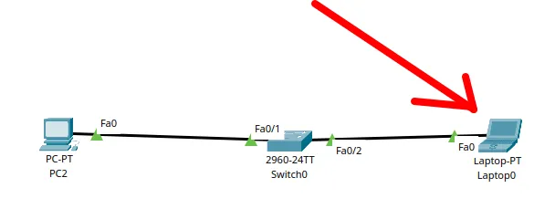
Then let’s click “Desktop” in the top menu and then click “IP Configuration” as shown by arrow 2. We are doing these steps to show another way to insert IP on end devices.

Now, let’s insert the IP configuration for the second device by following the steps below and shown in the figure below.
- 1: Here we will insert the device IP. In this case, the IP is “192.168.0.2“.
- 2: Here we will insert the mask of the network. In this case, it will be “255.255.255.0“.
- 3: Let’s click the output button so you can leave the configuration window.

Testing connectivity with ping in the Packet Tracer
To use ping to test connectivity, let’s double click on one of the devices. In this case we will choose the first computer.
Then let’s click “Desktop” and then select the “Command Prompt“, as in the figure below.

Now we can check the machine IP by the terminal with the command below.
ipconfig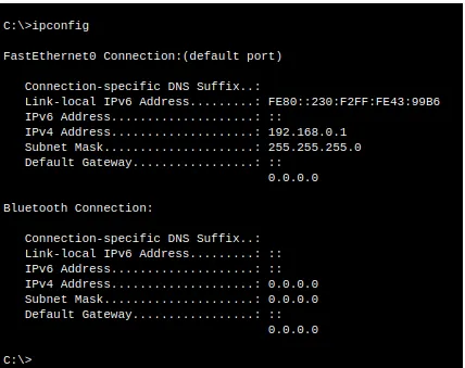
Now, let’s type the command below to do the connectivity test and then press “Enter”.
ping 192.168.0.2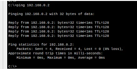
This command “ping 192.168.0.2” is being used to send a ICMP Package from the origin device “192.168.0.1” to the destination device “192.168.0.2″.
We can see that there was an answer and this indicates that we have connectivity between devices.
You can also test connectivity using the graphic interface with cards as we showed in this tutorial Here.
ARP table of a computer on the Packet Tracer
If you want to see the ARP table from a “PC” final device, we can make a ping following the previous steps and then on the same command screen, type the command below.
arp -a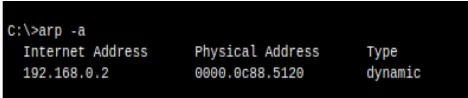
In this case, let’s see a screen like the one in the figure above. This figure shows the ARP table of the ping origin device.
In this ARP table, we can see the destination device IP “192.168.0.2” and the MAC of the destination device.
Checking the switch table
Now, let’s see the switch table. This part is very interesting and shows what we usually see in Switch theory.
To see the switch table, let’s double click the switch.
Then we will select the “CLI” tab, as in the figure below.
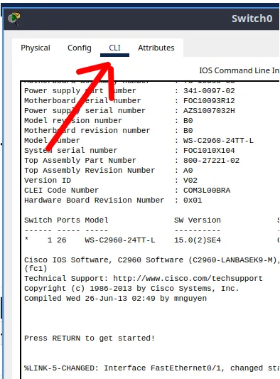
After pressing a “ENTER” or two for the prompt to allow writing, we will see the terminal as in the figure below.
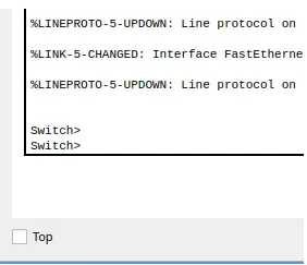
Now, let’s type the command below to show the switch table.
show mac-address-table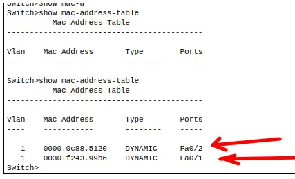
We can see in the figure above that the switch table shows the MACs of the two computers we inserted as well as the switch interfaces that we insert each computer.
See more:
- Lesson 1: Install Packet Tracer on Linux
- Lesson 2: Packet Tracer for Dummies: Setting Up Your First Network with 2 PCs (Quick Start Guide)
- Lesson 3: Create Network Switch packet tracer
- Lesson 4: Packet Tracer network with one router
Learn how to use the curl command: tutorial with practical examples
Tutorial: How to use WHOIS and RDAP
https://prelogin-authoring.netacad.com/courses/packet-tracer

Juliana Mascarenhas
Data Scientist and Master in Computer Modeling by LNCC.
Computer Engineer